New Valve Seat Cutter Handle

It was a dark and stormy night…

…OK, it wasn’t, but it was a wet, cold and windy afternoon of the type that does not inspire me to head out to the tent and work on the chassis.
My head was off being welded, the barrel was off being re-bored.  In truth there’s plenty to do, but I decided to deal with a nagging doubt, and practice my turning skills a bit.

As I’ve mentioned before, I’m impressed with the cheap Indian valve cutters I bought, but not entirely happy with the quality of the handle, which could effect the concentricity of the cut.
As it happened I had a nice bit of 16mm 303 stainless under the bench (left over from some abandoned project or other, I suspect) so it felt like time to build a new handle.
Now, I imagine I can build something like the original, but a bit better. On the other hand the only way to truly guarantee lasting concentricity would be to make in one piece. Yes, it would only fit 3/16” valve guides, but any bike I’m likely to work on in the near future has them, and it won’t cost me anything to make another one in a different size should the need arise.

So, step 1 was to identify the threads on the cutters. Actually, it’s easier to look at the ones on the handle. It was half an inch diameter and 20tpi, so according to my charts that should be ½” UNF. I could have sworn it looked like a 55 degree thread and not a sixty, but my eyesight is nowhere near that well calibrated, so UNF it is.

Step 2 was pretty much waste work. I wanted to know that I could actually reproduce it reasonably.
There was no waste material involved, because I just tried it on the end of the bar that would later be turned down to form the pilot.

20180120_142447

It was something of a joy to be working in stainless. I’ve done a few bits in mild steel recently and it’s virtually impossible to get a decent finish on it, especially with a little lathe, so the stainless boosted my flagging confidence a bit. Notice the digital readout on the cross slide. It’s made from a £5 digital tread depth gauge.
However, I digress, frequently.

Once the end of the bar was down to size it was time to run the lathe upside down and backwards, honest.  In the first incidence, little lathes are pretty poor at running parting tools, which is what’s needed to cut the relief at the back of the thread. The whole machine is just a bit too flexible for the forces involved, so running them backwards with the tool upside down reduces the consequences of chatter. Effectively the tool is pushed off the work, rather than digging in underneath it.

With that done it was time to cut the threads, when the backwards bit it even more useful.

20180120_150728

The problem is that, by definition, to cut the thread the machine must feed automatically, in sync with it’s rotation. There’s a little dial down by the leadscrew which allows you to re-engage the halfnut (that’s the drive to the longitudinal feed) such that it cuts in the same place on every pass. So you need to engage it at precisely the right moment, as the dial goes round.
Then, since a right hand thread feeds towards the chuck, you have to disengage it in that tiny gap between the end of the thread and the body of the part. If you don’t it all crashes, makes a hell of a mess, destroys the part and quite possibly some of the lathe gears…nasty.
With a very short thread like this one you’ve got maybe half a second or so to shift your attention from the dial to the tool and disengage it.
However, by running it backwards, it feeds away from the chuck, leaving you lots of time to overrun without damaging anything.

20180120_150627.jpg
The net result being a thread that fits the cutters very nicely indeed. Having never done that before, I was quite chuffed.

But then turned it all off again to make the pilot part of the handle. I didn’t turn it right down to size at this point, because I wanted a decent finish on it (which means using the down feed) and couldn’t be bothered to change the gears back from the threading pitch until I’d finished with them.

20180120_164337.jpg

With that done it was time to repeat the threading exercise and try it out with a cutter. Getting close!

Here’s a simple, but sneaky trick (well, I was impressed when I saw it) if you want to drill a hole nice and centrally through a round thing. Chop a bit off the end, bore a hole in it in the lathe, then use it as a guide… guaranteed!

20180120_174451.jpg

So, here’s the finished product, ready to roll.

20180120_175726.jpg

Cheap Indian Valve Seat Cutters Review

That is, cheap valve seat cutters from India, not cheap cutters for valve seats on Indians, though they may well work for Indians, of course.

Anyway, having established that an HSS cutter would function on the BSA valve seats, I decided to take a punt on a cheap set from India.
Perhaps it would be wise, at this point, to define “cheap”.
Assuming that we’re talking about doing the job by hand and not with a massive piece of custom built machinery, then the de-facto standard appears to be Neway. You can pick up a set of four cutters, with pilots and a handle for around £700 at the time of writing.
Moving down a notch you can get a similar set of three Sealey ones for £500. Aim for a wider selection and you pass the £1000 mark in very short order.
On the other hand you can get a set of 12 cutters, plus pilots and handles from India for £60. That will double if you want to cut modern hardened seats, but it’s still less than a single cutter from a reputable make.
To be honest, there’s no way I’ll ever get payback on a pukka set, I just don’t do enough valve seats to justify it, so it’s worth a punt on the cheap and nasty ones… or is it?

Well, they arrived in about a week and at first sight, the cutters themselves looked fine.

Screenshot_20180115-175615

The handles and pilots, perhaps less so. The threads on the pilots were poorly cut, which meant that they rely on the taper for good alignment with the handle. And concentricity between the pilot and the cutter is truly critical here. Alas, the way the handle was threaded meant that that didn’t work terribly well.

20180112_161308.jpg

20180112_161331

Added to that, the arrangement at the end of the pilot, meant that it wouldn’t go far enough up the valve guide to cut anyway.

20180112_161146

So far, not so good.

Not being one to give up lightly (especially having parted with money) I stuck the handle in the lathe and, firstly stuck a dial gauge on it to establish that the cutters do actually run true to the handle, which they do.

So then it was a pretty easy job to stick a little boring bar up it and make sure that it had a clean taper for the pilot to sit in.

20180112_172206

Then to turn down the big lump on the end of the pilot, so that it actually fits up the guide.

The next step was of course, to find out if it now worked. I have a bit to play with on my inlet valve (as I’m putting a bigger valve in) so I was able to give it a little go.
First, a light coat of engineers blue (am I the only one who always ends up looking like a fashion advert for woad as soon as I open the tin?) round the seat and then scrape it off with the cutter.

20180113_135558

Which did quite a nice even job of it.

The the next step was to cut it just a little bit more (to make sure I was seeing the true cut) clag some more blue on it, shove the valve in and give it a tiny lapping motion.

20180113_135711.jpg

Which transferred a pretty even coating onto the valve. For those who actually look at the pictures, that attempt had far too much blue on it, so I wiped it off and re-checked it, but forgot to photograph the result.

So, the conclusion?

The cutters work just fine, but not straight out of the box. If you have a lathe and can be bothered to fart around a bit, I’d say that this set are worth the effort. To be fair, even if I produce a whole new handle and pilot arrangement it’s still good value for twelve cutters at half the price of one posh one.

What I don’t know, is whether I got the Friday model or the Tuesday model. Looking at the workmanship on the pilots I’m willing to bet that they’re not fantastically consistent, but for me, worth a punt.

Reworking the B40 Head part 1

20180219_083129

Starting on the B40 head.

This is one of those moments when you really need to remember what you’re doing. There’s a huge temptation to get carried away and put lots of effort into a race prepared head that will last for nearly two hundred miles. That’s very much not what this bike is about though. As stated earlier, I’m after a bit more than a stock B40, but definitely without making anything fragile or maintenance heavy. It’s just a fun classic road bike, that can cope with modern traffic.

So, ‘ere (as they say) we go…
Firstly, like all good engineers (and bad journalists) I shall quote my main sources. Such head hacking knowledge as I have has been gathered over many years, from all over, but I guess the main names are David Vizzard, from way back in my Mini racing days, Graham Bell, probably from even earlier and Rupert Ratio (aka Dave Smith) for the BSA single specific stuff.
If you like to do your own research, then obviously Google is your friend, but beware that any idiot (like me for example) can publish on the web these days, especially on the various forums. I find the best bet is simply to never trust information that hasn’t been corroborated by more than one source, and make sure that the second one isn’t quoting the first!
Some of this information is, of course thirty or forty years old. Fortunately, despite all sorts of trends in tuning, fluid dynamics hasn’t changed, ever. There is the occasional advance in our understanding or measurement of it (like when boundary layers were first understood) but they’re pretty rare. Most of the advances in tuning are to do with electronics these days and the others are about materials and manufacturing capability.
Remember, this isn’t about motogp or dragging the last possible 0.01% out of the engine. Solid, proven engineering will be fine.

There are two very good bits of news about the B40 head as a starting point. Firstly, the combustion chamber is a pretty good shape. It’s a classic hemi head (as in hemisphericalish) which generally makes for good gas flow.
The second bit of news is that the ports are pretty rubbish. That means that there’s some nice “low hanging fruit” to be gained in terms of releasing power.

On the subject of starting points, I’d already decided to go to SS90 valves and a 30mm flat sided carb before starting and managed to get hold of a pair of N.O.S. valves off the web. A quick note of caution there. Even if you’re collecting bits for a future build, make sure you check them straight away. One chap on ebay (who called himself an expert dealer) tried to flog me a C15 camshaft as an SS90 one, so make sure you’re getting what you’re paying for.

Obviously, the first job is to assess what you have. This is what I pulled off the top of the engine.

20180105_181755

And this is what it looked like once I’d cleaned it up a bit.

20180106_173138

The condition of what you have may well decide what order you now proceed in. In my case I had two questions to answer up front.
1) How hard are the valve seats?
2) What sort of condition were the valve guides in?

Here’s the logic behind that. Some people recommend that on B40s you shouldn’t change the valve guides unless you need to (even to the extent of having them lined) so I wanted to avoid it if possible. They’re cast iron guides, which wear pretty well, and the rest of the engine has so far proved to be in surprisingly good nick.
So I needed to know whether to order up new guides, plus appropriate reamers etc.

As for the valve seats. I intend to cut my own (that way I stay in control of the fine detail) and if the seats are hardened I’ll need carbide cutters. If not I can make do with cheap HSS ones. If I were richer I’d just buy a modern set for £500-£700, but I’m not, so I’ll take a chance on a cheap set from India.

This is an ancient Sykes Pickavant valve seat cutter that I got for a tenner at some autojumble, years ago. Sadly it’s about 1.5mm too small for the new inlet valve, but at least I can see if it cuts the seats…#

20180105_123406

…and it does, so HSS cutters it is and I can get them ordered.

20180105_181755.jpg

And so, to the valve guides. There’s loads of information on the web about the correct clearances for valve guides (generally between 0.0012” and 0.0015” for a 5/16 stem) but very little about how to measure it. My smallest bore gauge is about 3/8”.
The trick I learned is that if you put the valve in the guide dry, you should be able to feel some wiggle in it. If you then put a thin coating of oil on the stem and put it back, the wiggle should disappear. It’s a much more accurate test than you’d imagine.
Both of my guides passed that test with flying colours, using the old valves and the new ones (with cast iron guides the valves tend to wear more than the guides anyway) but that didn’t take into account anything I might remove from the new ones whilst preparing them. So my first job was to be sorting the valves themselves.

These are 1960s/70s BSA parts, so don’t expect anything beautiful. You could lap them in and they’d work, but you’d wear out the valve guides really quickly and re-profiling and re-finishing them should yield a significant improvement in efficiency.
The inlet valve took me about two hours, but I wasn’t rushing and remember that the head is where all the power is made and tiny differences in geometry can make big differences in gas flow.

The inlet valve.

There are basically two shapes of poppet valve. There are mushroom valves and nail valves. A mushroom valve has a convex back face (like the top of a mushroom) and a nail valve has a more or less flat back face (like a nail).
Mushroom inlet valves work well on hemi heads. Personally I picture the gas following along the curve of the valve head, then continuing along the curved surface of the combustion chamber, so it sort of fits.
For flat combustion chambers, nail inlets work better. Again for me, I just picture the flow being sprayed out flat from the valve head (a bit like a lawn sprinkler) and following the flat surface of the combustion chamber. I’ve no idea whether that analogy is accurate in terms of gas flow, but it works for me.
So the B40 inlet is a mushroom valve. It’s not a hugely pronounced curve, but it’s there. On the factory fresh valve it then has a 45 degree seat turned on it, below which is a flat area called the margin.

valve

The whole thing is finished fairly roughly and mine had a few tiny nicks around the edge, which I reckoned would both disrupt the gas flow and be centres for build-up of heat and carbon. The valve proportions I’ve used are from Graham Bell (who backs up his assertions with lots of flow bench work) but slightly modified, which I’ll explain as I go.

I started work on the face and head of the valve, primarily so that any marks the lathe chuck left in the stem would be removed when I refinished that bit.

The margin should be between 0.040” and 0.065” deep. This gave me scope to remove a fair amount from the face of the valve and thus get rid of the nicks in it, without going right down to the minimum. In a race engine, losing the tiny bit of mass and potential clean flow that a minimal margin would achieve would be worth it. On the road it’s safer to leave everything a little bit chunkier (for strength and cooling) but not as chunky as the original part, which was about 0.075.
I ended up with about 0.050”. Tiny differences really do make a difference when shaping valves.
For the inlet valve, the bottom of the margin, the angle between the margin and the face, should be sharp. This is to disrupt any tendency towards backflow.
So my first cut was to take a chunk off the valve face. I’m not sure what the composition of the steel is, but an HSS lathe tool came off worst in the encounter, so I switched to a carbide one.

20180106_181243.jpg

The next job was to polish the face. I ran the lathe at about 2400rpm starting with silicon carbide paper (wrapped over a sponge to conform to the shape and stop my finger burning) and working my way down from 120 grit, through 400, 800, 1200 to 2000, then polishing compounds (black , green then white) applied directly to the face, then burnished with a J cloth.

20180107_114502.jpg

Finally, a very light touch with the lathe tool again, just to re-sharpen the bottom edge.
With the face done I made a 30 degree back cut, bringing the width of the seat down slightly and blending it into the back face. It’s only a small cut but, again, makes a difference.

20180107_120153.jpg

the width of the actual seat is a matter of some debate. 0.075” seems to be standard for race engines, but I prefer to leave a bit more on road engines, which are not expected to require rebuilds every few hundred miles. Just be careful how you match it to the seat, but I’ll come to that later when I cut the seats.

Once the face and back cut were done I chucked up a piece of scrap aluminium, which I faced at both ends and drilled for a centre to provide two perfectly parallel faces. The idea was that, once I had the valve running true to within a few microns I could force the aluminium against the valve head with a live centre, thus providing decent support as I worked on it.

20180106_175911.jpg

The stem needs to be polished in exactly the same way as the face was, except that it’s a much easier shape. Just make sure that you use a bit of wood, rather than your finger, when working near the chuck. Reducing the diameter of the stem, below the guide, by 0.035” and tightening the radius of the bend onto the face to about 10 or 12% of the head diameter will yield about a 10% increase in flow at very small valve openings. It’s only a small part of the cycle and personally I prefer not to on road engines, again to improve cooling and reduce the chances of the valve bending or snapping, both of which have happened to me in the past.
The result should be very shiny. You can still see circular imperfections on the head of mine, but it feels perfectly smooth to a fingernail and looks smooth under a magnifying glass, so I’m not sure how far I’d have to go to remove them.

20180107_144254

The Exhaust Valve

The exhaust valve is a horse of quite a different colour, for two very sound reasons.
Firstly, it doesn’t really have to concern itself nearly as much with fluid dynamics. If you think about it, the inlet charge is being dragged kicking and screaming from a nice cool world into a very hot little hole. The exhaust gasses, by comparison, are not only being shoved out by a thumping great piston but are also desperately trying to find somewhere to expand to, so apart from some finesse in maintaining the exhaust velocity, one can pretty much assume that it’s keen to get out.
Where the exhaust valve does have a real issue is simply survival. It’s operating at temperatures upwards of 800 deg C, so not burning up is its main concern.
In shape it wants to be a nail type. We’re simply looking for as big a hole, as soon as possible when it opens, and the roughly concave surface (if you include the curve up to the stem) naturally turns the gas up into the port.
We can leave some extra meat in the head compared to the inlet (any thin bits may burn up) and a margin of 0.060 to 0.100 will give the best flow. The angle at the bottom of the margin should be radiused in the exhaust, the gas is flowing outover and we don’t want to disrupt it.
A wider seat of 0.080” or more (which is its only solid contact with the head) will help a lot with cooling.
Reducing the stem near the head is the same as on the inlet and, again, I chose not to. It still wants that 30 degree back cut and, just like the inlet valve, the more polished the finish, the better.

The Combustion Chamber

As I said at the beginning, the B40 combustion chamber isn’t a bad shape at all. It’s a nice smooth shape with no nasty pocketing or obstruction of the valves and nothing to obstruct gas flow or flame front. Even the plug sits nicely flush with the surface, so there’s no shrouding of the spark.
Being happy with the shape, the next question has to be condition.
Once the carbon was cleaned off it had clearly had a moderately hard life.

20180107_144522.jpg

I’m not sure what bit it here, but it does look like a potential hot spot, which could cause detonation.

20180106_173159.jpg

All in all, I wasn’t sure how far I wanted to go with this head. I had a sneaking suspicion that if I were to take all the deeper scratches out I may well remove enough material to be doing more harm than good. To be honest, I’m still not sure and may well go back to it later, but for now I’ve contented myself with a reasonable clean up and light polish.
Putting a perfect polish on the combustion chamber doesn’t actually do all that much for performance (especially once it’s done some miles and has carbon on it) but does reduce the ability of carbon to stick to it, so it stays cleaner for longer.

20180107_155441.jpg

Next up, the inlet port…

Stripping the B40 Engine Part 2

20171105_163431

The timing side

20171105_160354

The outer timing side cover is a doddle on the B40, because that’s all it is, a cover. Beware though, on some of the BSA’s (and Triumphs I think) when you remove it, the whole kickstart assembly goes Boing! powered by the rather forceful spring.

The big nut is on the end of the camshaft and, despite it’s size and impressive appearance, is only there to control end play and disappeared on the later models.

There’s a goodly selection of screws in the inner case. The only one that causes a real issue is the one on the kickstart spring, which has a little steel reinforcement piece on the other side, which will drop off and try to hide under the bench.

20171105_163408

Once the inner timing case is off, it all looks a bit scary…

20171105_163431

The guts of the gearbox should actually come out with the inner timing case (it certainly goes in that way) but mine didn’t, so I just pulled it out and stuck it in the obligatory takeaway box. Don’t forget the little spring bolted to the back of the casing

20171105_165454

the camshaft and the cam followers seemed like a sensible next stop, followed by the distributor drive, which needed gently tapping out with a brass drift. All pretty easy going really, but lots of pictures will help it go back together.

20171105_172310

Then the nut on the end of the crankshaft and the drive gears for the oil pump and distributor.

You can now get at both sides of the gearbox sprocket arrangement and remove that…

20171110_171041

And you’re down to the crankshaft!

Remember to remove all the nuts holding the crank case halves together OK, I know you’re not stupid, but one reader might be. Let’s face it, if he/she’s relying on my blog for intructions…

Anyway, I used a nice store bought crankshaft pusher/puller. Essentially it’s a big bit of plate that bolts onto the alternator mounts, with a top hat thingy through the middle and a big bolt to push down on the crack shaft end.

20171110_174909

That pops the primary side case straight off, the crankshaft comes out of the timing side bush pretty easily

20171110_180530

all you’re left with is the timing side case in the stand.

Job done!

Now to start the real work…

The B40 Rocker Box Refurbished part 1

20180127_130611

20180204_155719

A simple(ish) little job, but nonetheless one that has to be done. Well, some of it has to be done and some if you only do if you’re an idiot who like shiny things.

20180121_160921

Whipping off the tappet adjustment covers is pretty obvious. As is the single nut that secures the decompressor. Actually the decompressor lever took a bit of levering off, but only due to years of claggy oil.

Now then, the rocker shafts on most of the BSA singles are an interference fit, or at least extremely tight, so you’ll have to use heat to remove them.
First whip the cover off the side ( thirty seconds with a screwdriver) Then it’s a good idea to clean and degrease the whole thing as best you can. Or you’ll stink the oven out.

20180121_174539

Slap it in the oven, set it to 180C and when the oven’s up to temperature, so’s the casting.

20180121_174747

And you only need a tiny soft faced hammer (I made mine out of a bit of re-bar and gave it one aluminium face and one nylon one) to tap them out. Be careful tapping on the threaded end. There is a centre drilling that you can stick an old phillips screwdriver in if you’re nervous about it.
Make sure you keep the shafts in the right place until you get them labelled, they’ve been in there a long time and won’t want to be swapped over.

20180121_182949

While it’s hot, take the opportunity to remove the hollow locating lug(s) as well. You’ll notice that the box looks very empty on this picture, which is an optical illusion and definitely not caused by me forgetting to do so and having to heat it up again.

The rockers themselves just pull out. You’ll have to take the exhaust rocker out before the decompressor shaft, which you might have to fiddle a bit to get it clear of the rocker end.
Old fashioned tie on labels are great for this sort of job, because the string enables you to keep all the springs and spacers in the right order.
There is some debate over whether I’ll use those springs (Some say it’s better to make up accurate shims) but I’ll deal with that when I get to reassembly.

20180121_180334

Having got the casting cleanish and empty, I was able to get a good close look at it. At a quick glance and before cleaning it I’d pretty much assumed that the bikes owner really wanted a Honda and, not being able to afford one, had taken out his resentment, starting every day by picking up his favorite spanner and dealing it a firm clout across the rocker box. How else could it have got so battered looking?
Alas, a fine story though it would have been, I don’t think it’s true. In fact, looking at the rocker box probably affords one a very good insight into the general state of BSA in 1962.
It works, but it’s appalling!

20180121_183401

It’s one thing to leave it rough cast (though I think the back may have a had a cursory swipe across a linisher) but look at it. If you look at the two “flat” faces in the picture above, one looks like a reasonable cast surface while the other one looks like it’s concrete set in raw plywood shuttering…and they’re on the same casting. The surface on the top is as bad or worse and…

20180121_183417

There are voids in it. This last is the most worrying, because it’s impossible to tell whether I’ll be able to take enough material off to make it smooth, without opening up more of them.
That should really be a good enough argument for me to give up on polishing, get it aquablasted and point out to observers that it’s in aid of originality, but I’m not going to. I’m sure the job will be far more effort than it’ll be worth, but I want it shiny. So there.

I went into polishing ally a bit when I was blogging about Little Suzi and the technique hasn’t changed since. It’s simply a matter of scratching the surface off with increasingly fine abrasives, until it looks nice and shiny and smooth.
What also hasn’t changed is the moment when you really regret starting it and think it’ll never look decent again!

20180127_132759

I started with a detail sander, using 80 grit, then 120 grit. That’s as fine as standard abrasives get for the thing, but I did find some hook and loop 400 grit that I could cut to size, good ole fleabay again!
The detail sander leaves a finish something like this…

20180127_141201

,

A bit drastic, but flat, and it was necessary to remove close on 1mm of material to get past all that rough casting, so drastic measures were called for.
Now, at some point in that process, you may well accidentally leave the sander still for too long. When you lift it off, you’ll see a really neat geometric pattern and, if you’re mind is anything like mine (and if it is, God help you) you’ll think “Ooh look, that must be how they do the pattern on that fancy engine turned aluminium sheet that they make racing car dashboards and such out of.
Do NOT try leaving still for a few seconds longer to see how the pattern develops. The little circular grooves take bloody ages to sand out again!
Once over that error, one naturally assumes that there must be a really clever way of getting into all the little corners.

20180127_141223

No there isn’t! or if there is, I don’t know it. I used a rotary tool (cheapo dremel-alike) and a whole range of abrasive drums wheels stones and cutters. Even then you will end up with little bits of wet and dry in your (sore) fingers, scraping away.

20180204_125822

This is the main range of attachments I used. That bottom one was very good, but a bit costly (£20 for ten). They come in a good variety of grades and consist of paper wound onto a 3mm or so mandrel and glued in place. That means you can unwind them to the desired diameter for tight corners.

Once the limits of the detail sander are reached its down to using the “dremel” on the whole thing, which gets one to about here…

20180127_144024

You’ll notice, now, that one of the gasket faces for the oil feeds was starting to look perilously thin, by the time I’d taken off enough material to get it smooth.
My intent was to cut that back at the end to create a big enough face and it worked out fine. I didn’t take much, so there shouldn’t be a need for an extra gasket.
From here on out it’s pretty much down to hand sanding with wet and dry down to 2000 grit, before hitting the buffing wheel.
Speaking of which. If, like mine, your working area can be described as “compact and bijou”, you’ll find it well worth investing a few pennies (literally) in some of these…

20180204_115758

They’re simply a giant woodscrew on the outside and a metric thread (in this case M8) on the inside. What they do, however is allow one to quickly mount and dismount bits of kit to your bench, without resorting to annoying and unreliable clampery.

20180204_121147

I got the motor for my buffing wheel from a junk stall at the local market and the abors, wheels and various compounds I bought as a kit at one of the classic bike shows. Brown and blue compounds are all you’ll need for ally.

20180204_142344

Having got the thing pretty much shiny, though you can see there’s still some detail work to do at this stage. It’s time to remember that the most important surface on the whole casting won’t be seen. Namely, the gasket face.

It’s quite hard to show how uneven it is on a photo, but one side of the centre section was very badly scored and, probably more to the point, somewhat lower than the rest of the surface.

The answer is plate glass. I use a glass chopping board that I got for a fiver.
Traditionally, one would coat the surface in grinding paste and rub it against the glass in a sort of figure eight pattern. Nowadays, people tend to tape a piece of wet and dry to the glass, which is less messy.
I tried both and found the grinding paste to be more effective, but it left me paranoid about getting it all cleaned out. Lets face it, any trace that’s left is guaranteed to find it’s way into the oil system, lodge somewhere sensitive and destroy the entire engine.
What I found quite interesting was how it looked after a couple of minutes.

20180204_151247_001

So the gasket face was obviously curved and won’t meet at all around that stud, but it doesn’t take too long to get it looking uniformly grey and dull, which is how it should be. There’s no need to polish it, as long as it’s flat. In fact, I’m not sure whether a shine would be counter productive. I’m a big fan of blue Hylomar and I reckon it’s probably better with something to key to. No doubt somebody who knows what they’re talking about will soon correct me.
Anyway, it ends up looking like this…

20180204_154908

Assessing the BSA Barrel

As I mentioned earlier, one of the first jobs I need to do is to figure out whether a rebore is required and, if so, by how much.
Getting hold of SS90 pistons can be an exercise fraught with danger and frustration, so the sooner I can start the process the better.

The easiest place to start is with the piston. The standard B40 piston is 79mm in diameter. This is odd on an imperial bike, but it’s what BSA quoted, because the capacity is cubic centimeters. It’s even odder when you’re looking for an oversize one, which will be quoted as 79mm plus the overbore in thousands of an inch e.g. 79mm +20thou (0.020”).
Only on British machinery does one find this type of eccentricity.
Fortunately I’m of that peculiar age that grew up as we converted from one system to t’other, so I’m largely ambidextrous when it comes to measurements.

However, I digress. The standard piston is 79mm (just in case you’ve forgotten) so if I measure mine it will give me the first clue as to whether its been rebored before.

20171028_150552

And it mics up to exactly 78.9mm, so that’s a standard piston. Mind you, I have seen people put a standard piston back into a +20 bore!

Getting to the barrel itself, the first task is to remove many years of grime. My preferred method with cast iron is fairly brutal, but effective. Boil it in caustic soda. Hence the traditional Glaswegian insult of “G’away an boil yer barrel, Pal”
I guess I need to put the health warnings in here. Big gloves and eye protection are definitely the order of the day (and I’m not just writing that to stop people suing me, it’s really very nasty stuff) and for goodness sake don’t put anything aluminium in it, or it’ll dissolve before your very eyes. Oh yes, don’t use an ally pan either!

Before you actually start the thing simmering, you also need to figure out how you’re going to protect it afterwards. Hot cast iron flash rusts at an unbelievable rate, so you need everything ready for when you rinse it off.
I left my BSA soup simmering for about an hour or so and must give massive credit to my long suffering girlfriend who, when I told her I was setting up the camping stove in the yard, told me to do it in the nice warm kitchen instead.
You’ll notice that I left a couple of studs in it, purely to make it easier to handle.

20171029_161438

Once you reckon it’s done, you need to rinse it off with boiling water. Cold water will remove the caustic, but it’ll leave the barrel wet. Boiling water on a hot barrel will evaporate virtually instantly.

My choice of protection is a couple of coats of Granvilles cylinder black for the fins and a wipe over with WD40 for the bore and the gasket faces.

And here’s the proof, the thing actually rusted faster than I could paint it!

20171029_181746

At this stage I just carried on painting. To be honest it’ll probably be fine like that, but I’ll have a look when I get around to using it.

So, we now have a clean barrel.
Check one is purely visual.

Reasons to be rebored 1…2..3.. (Ah, Ian Dury, one of the finest!)
If the barrel is significantly scored (especially grooves cut by a loose gudgeon pin or circlip)
If it’s significantly rusty i.e. more than will wipe off without effecting the finish.
If it has a ring around the top, where the rings come up to, that you can feel with a fingernail.

Mine failed on the last one, as you can see below.

20171029_210019

A colour change at that point is quite common and may not be a problem. If you think about it above the line is effectively combustion chamber, so it will have been in a very different environment. But if you can actually feel the ridge with the end of your fingernail, it needs sorting.

If it hadn’t already failed at this point I’d have gone on to measure it up for wear, taper and ovality. As it had, I still needed to, to establish just how much of a rebore it needed.

Measuring the Bore.

Unless you have a very large lathe and a dial indicator, the only way I know of to measure a bore is with a bore gauge.

Actually that’s already not true because, strictly speaking (and I’m sure there are many of you out there just as sick and pedantic as I am) a gauge cannot measure anything.
A meter can measure, i.e. give an absolute figure. A gauge can only give a relative measurement. So, for example, a vernier gauge can tell you how far its tip is deflected, but not where it was in the first place. So if you take a vernier gauge and then stick an anvil a known and precise distance from it, you now have a micrometer!

The upshot of this is that one must first calibrate the bore gauge against a known value and, given that it only has a range of 5mm, it has to be something pretty close to the bore size.
Some people use the piston size, I set it against a micrometer set at 80mm, which is about the maximum bore I could expect. It’s done by simply plonking it in the micrometer and setting the gauge to zero.

20171103_104641

Incidentally, you will never, ever (even if you’re sober) be able to hold a bore gauge normal to the bore well enough to get an accurate reading from it. It will tilt one way or the other, or both.
The answer to that problem is really simple, once you know it.
At any angle other than perfectly normal the distance covered by the gauge will be greater than the true diameter. Therefore, if you rock the gauge slightly from side to side, the reading at which the needle reverses must be the right one. It’s easier than it sounds.
Oh yes, and the readings are backwards. If the plunger on the gauge is pushed in by 1mm, that means that the bore is 1mm less than the reference, so the gauge reading needs to be subtracted from the reference to get a true diameter.

So having set the gauge, we then stuff it down the barrel.

Alas, when dealing in microns, the barrel is quite a large area of real estate. So you may well ask where exactly in the barrel do you stuff it.
The answer is pretty much all over the shop. Actually, we take readings front to back and side to side at the top, in the middle and at the bottom.
I stuck together a quick spreadsheet (don’t you just love a nice spreadsheet) that I could plug the readings into and get the maximum and minimum piston clearances, the maximum taper and the maximum ovality out of. Any of these can be cause for a rebore, if they’re too far out.

20171103_104908

Here are my results

results

The key figures here are the max and min piston clearances. You can see that they’re almost exactly twice the allowed tolerance, so it’s worn.
However, that 6 thou is only 3 thou over, which means that a first oversize of 20 thou will be more than enough.

Ergo, I need a plus 20 piston and a rebore to match it. Now all I have to do is find one, which is a whole nother story.

BSA B40 Engine Strip Part 1

Let’s face it, pretty much every rebuild starts the same way. Flip the ratchet to “undo” grab a handful of spanners and start ripping the thing apart.

Actually, now I think about it, it’s a bit more than a handful of spanners. Somewhere in the job you’re going to either need, or find the job much easier with, one or more special tools.
I seem to remember as a callow and impecunious teenager managing to rebuild a C15 and a Cub without having any, but it usually involves a fair amount of swearing, wasted time and, very probably, damage to components.
It’s a matter of choice how far you go and where you get them. Most are relatively easy to buy nowadays and many you can make yourself, so it’s a toss up between whether it’s cheaper/easier to make, buy or adapt something else.
I was a bit lazy on this job and bought two. One was a clutch puller and the other a crankshaft pusher/puller. I could have made both, but it wouldn’t have saved a lot of money, by the time I’d bought materials (none of which I had in my usually reliable scrap bin) and would have taken a fair bit of time and effort.
In short, make sure you’ve got what you need up front, as it’s really frustrating losing a valuable weekend because you can’t get the right tool until Wednesday.

Being the beginning of the job it’s easy to be overenthusiastic and believe that you’ll remember where everything went, not to mention what it was, because when you’re looking at it in situ, it’s blindingly bleedin’ obvious. I promise, that in a few months’ time it won’t be, or at least it never is for me. So gather your tags, boxes, bags, pens and camera/phone and document the thing to death. It’s always a good plan.

Starting at the top I whipped off the push rod inspection cover, just for a quick look. It’s worth noting which push rod is which (red for exhaust in this case) then it’s off with the rocker box.

20171027_161810

20171027_162726

A quick look reveals a bit of wear on the tappet adjusters, but nothing horrid. They’ll be replaced anyway.

Now, we all know that in every such job there is a stud which decides to come out with the nut. In this case (naturally) it had to be the one stud that didn’t have enough clearance to come out.

20171027_164148

One answer would have been to ease the head off a bit at a time, but it would still have been stuck there, because it can’t come out of the head upover. I figured it was better to sort it now than end up with it stuck in the head, so I flooded it with easing oil, wound it out until it was jammed against the rocker box stud and that held it enough to free the nut.
Take note, you need a bit of a sympathetic hand to do this, there’s always the possibility, if you rive at it hard enough, to strip the threads in the crank case, or possibly crack the head where the rocker box stud is.

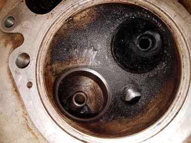
Once off, the head didn’t look bad at all for such an old bike…

20171027_165425

and neither did the piston crown.

20171027_165429

One could easily suspect a top end rebuild in it’s recent history.
The barrel follows pretty naturally, then the problem of the piston arrives. By all means have a gentle shove at the gudgeon pin, but if it comes out it’s knackered. It should be a very tight fit. Oh yes, don’t forget to take the circlips out and don’t even think about re-using them.

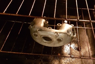
The answer lies in the kitchen. Moving with the stealth of a cat burglar the intrepid spanner spinner needs to stick the kettle on and, without making any sounds that could give him away… steal a tea towel!

20171028_144625

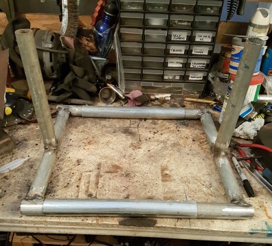
Wrap the tea towel (not the souvenir Charles and Dianna one) around the piston and pour a kettle full of boiling water over it. The tea towel will retain the hot water for long enough to expand the piston and the gudgeon pin should just push out, or at least require only a very gentle tap. It did too! You’ll notice from the pictures that the rotating engine stand really does make these tasks easier.

All these bits, by the way, are making their way into takeaway boxes and labelled plastic bags, as I remove them, so there are no piles on the bench.

I can never resist giving the con rod a bit of a wiggle about at this point. You’ll be able to move it side to side a bit, but it should have no detectable up and down play at all. In practice, it’s quite hard to tell the two apart until you get used to doing it. One trick is to hold the con rod tightly in one hand and pull it up as hard as you can (at top dead centre) then, with the other hand, clout it quite hard on the top. If there’s play you’ll usually hear a “clonk”. That test works even better with the crankshaft out and dangling off the rod.

With the top end duly packed away, my attention turned to the primary drive side, primarily because the engine happened to be that way round.
I’m a big fan of the traditional “cornflake box” method of storing case fixings. Simply draw the case on a bit of cardboard, poke some holes in and stick the bolts in the appropriate holes as you take them out. The takeaway box stops them slipping out.

20171105_144611

Incidentally, I believe in doing this even if you’re planning to replace them with a nice shiny set of stainless allen head bolts. The main reason being that you can still see which ones are which length, without getting all but one of them in and then finding out it’s too long for the only hole you have left.

While we’re here, I think the subject of nice stainless bolts is worth a bit of a digression, though really, I suppose it should wait for the rebuild bit.
It’s very easy to assume that replacing as many fasteners as possible with new stainless ones is the best way to go. Sometimes it is, but in each individual case you really need to consider the side effects.
For primary case bolts I almost certainly will go to stainless allen heads, but there are issues to be considered.
The first is that one can exert far more torque on an allen bolt than one can with a cross head screwdriver. This can have one or both of two different effects.
The first and most obvious, is the possibility of stripping the threads in the aluminium case. Nuff said on that.
The second, and much less obvious, is that it can cause oil leaks. Yes, you read that right, tightening the case too much, even perfectly evenly, can make it leak. I really wish I’d known that all those years ago when I had my first C15 and couldn’t for the life of me figure out how it kept getting leakier the more I tightened it up.

It works like this…

Once you get past a certain tension on the bolt, it not only pulls the outer case down (or “in” if you prefer) but also pulls the inner case up, or out. The result is a little volcano shaped mound around the hole, where the threads have deformed the case.

bolt

Much exaggerated it would look something like this. If you have an old leaky case, try taping a bit of fine wet and dry to a sheet of flat glass then rub the gasket surface on it a little bit. You may well see such mounds come up clean before it gets down to the flat surface. In fact, if you do, keep going until it’s flat again!
Instinctively, I wouldn’t have thought it would be pronounced enough to overcome the give of the gasket, but I’ve seen it a few times and it certainly can. I suppose logically, this is a BSA and, as such, doesn’t need a second invitation to spring a leak.

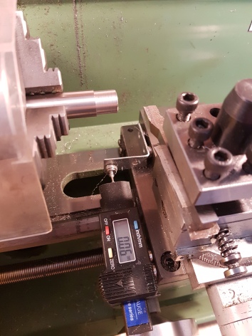
And, just in case you don’t believe me, take a look at the holes where the carburettor studs went.

20180218_152022

Another potential problem with stainless bolts (though less so on the primary case than in some other applications, particularly cylinder head bolts) is that they’re nice and shiny. I know, that’s largely the point, but shiny is also slippery and stainless steel bolts are much more prone to vibrating loose than ordinary ones. Nowadays, the wonders of Locktite will largely mitigate the problem in most cases, but you still need to keep in mind that it’s there and needs to be dealt with.

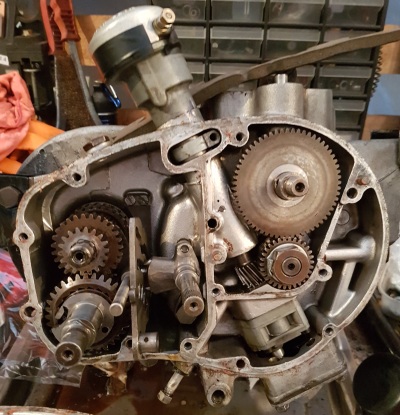
So, where was I? Oh yes, the primary side.

The first thing I noticed, here, was just how clean everything was. It’s a theme that continued throughout the engine strip and has me strongly suspecting a recent rebuild, but the chap I bought it off didn’t really know it’s history, so I’m not going to trust anything. Anyway, a bad rebuild can be worse than none, though I’ve no reason to suspect bodgery here at all.

20171105_144505

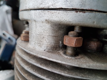
The alternator stator is just three bolts then you reach the big nut, on the end of the crank shaft, that holds the rotor on. There’s a tab washer to flatten (I still do it gently with a screwdriver and a hammer) then there are two problems. Firstly, it’s ruddy tight and, secondly, the crank shaft goes round and round rather easily.

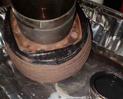
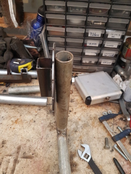
The second problem is solved by putting a couple of bits of wood over the crank case throat, to protect it, then sticking a big bar, wrapped in gaffer tape, through the little end. The reason it’s a big bar is to prevent it putting a groove in the little end bearing and the gaffer tape is to protect it’s surface.
for the tightness, I use a huge breaker bar. Mine’s nigh on three feet long. Now this will allow far more torque than I’d really like to apply to any bit of BSA, but it allows it to be applied very easily, and that’s important. If you have to clobber the bar, or jerk it, or lean on it, then you’re not really in control of how much torque you’re applying to the job. A nice, gently increasing pressure allows you to keep control and you’re far less likely to break something, unless you’re a ham fisted idiot, of course. In general, I really don’t like hitting things, well not motorcycles anyway.

20171105_150448

Once that’s out of the way, the primary chain tensioner just pulls off. A label with string on is good for keeping the spacers in the right order.

Then it’s clutch time!

Start with the biggest screwdriver you can find to remove the springs. They’re not horribly tight and seldom go flying about the place. You’ll notice that one of mine was a wee bit mangled. Again, they’ll be replaced.

20171105_151151

Once that’s done the cover comes straight off and you can fernagle the plates out. They never give up easily. I angle the engine downover a bit and use two small screwdrivers, at opposite sides of the plate to encourage them out.

Then it’s the other big nut, which gets exactly the same treatment as the last one. Looks like someone’s had a hammer and chisel to it!

20171105_152230

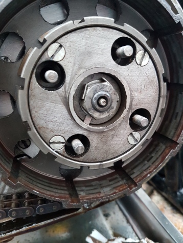
The exception to my dislike of hitting motorcycles is when they have machine screws or slot or cross headed bolts in them. I virtually always use an impact driver. Partially because it drastically reduces the chances of mangling the head and partially because mine actually has far better tips than any of my manual screwdrivers.
In this case I was applying it to the four screws that hold the clutch centre in, none of which were a problem.

20171105_153500

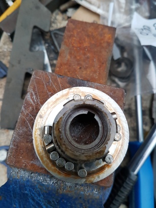
The thrust washer and clutch rod come out easily and then I allowed myself the luxury of using my store-bought extractor to remove the clutch centre.

Then you can pull off both ends of the primary drive, but be ready to catch all the rollers from behind the clutch.

20171105_153720

The job is definitely underway!

Building a Rotating Motorcycle Engine Stand

20171022_160216

Since time immemorial, I have stripped and built engines on the bench or on the floor…

…and it’s a royal pain in the backside. Trying to balance the thing at suitable angles, hefting it about, running out of hands at every turn and of course, that searing pain when you realize which part of your anatomy it was resting on when you hit it.

But no more, I say! Rupert Ratio has a drawing for a decent one, which you can lay on its side, in the back of his book.
Before embarking on production I had a quick look at fleabay (it’s often cheaper to buy than build) where I saw a truly snazzy one which rotated through about 300 degrees.
On closer inspection, it had a couple of drawbacks. One was a fairly substantial price tag and the other that the rotation was locked by a bolt through a radial slot in a circular plate. This means that only the friction applied by the bolt would be holding it, which just didn’t sound quite enough when you start riving on the thing with a big bar, or even have to tap something off/out.

However, this is the backyard builder and suitably inspired I headed for my various scrap bins to see what I could find…

I have to confess that I bought some bits. Actually two steel discs (offcuts on fleabay, presumably out of the middle of something with a hole in) and two M10 nuts and bolts.

To action!

The steel discs were marked out thus…

20171006_131351

For marking out rough stuff I love my little white paint pen. It’s nowhere near as accurate as engineers blue and a scriber, but a lot less messy.

Then bolted together, stuck in a vice and attacked with an angle grinder.

20171007_115016

A chunk of square section provided the next bits. Chopped up and drilled as below…20171007_123626

A quick zap with the welder renders all the nuts captive… then the channels get glued to the discs

20171007_124708

20171007_125510

Now I need something to hold them off the ground…
I cadged half a dozen four meter lengths of this heavy walled tube from some chaps who were chucking it in a skip. It used to be handrail in an industrial unit. Keeping your eyes open and have a bit of cheek can save you a fortune.

20171006_174414

But beware, welding galvanized steel produces lethal fumes. I make sure I grind all the zinc off the outside and since I don’t have an enclosed space to weld in I reckon being a bit careful will do for the bit on the inside. You may want to clean that off too.

Once it was tacked together I chopped it in half…

20171006_174838

Because, by a fortuitous miracle I just happened to have a few yards of this size tube as well

20171006_175315

Which is what I’d call dead jammy.

So, with a couple more bits stuck on, I now have an adjustable width standy uppy bit, to stick my roundy roundy bits to.

20171006_183647

Now, if you’re going to build one of these, I suggest you ignore the next bit, because it’s where I came up with a stupidly complex solution to a very simple problem.

I bolted the disk to the upright, so far so good…

20171007_161418

Then produced this natty little pawl mechanism, involving lots of cutting and folding, which I welded to the top of the pole.

20171007_172142

And it works a treat. BUT…

If I’d just left the pole a bit longer (like I did on the other end) it would have been a helluva lot simpler…

20171014_164424

To just stick the pawl in a slot in the pole. Then fashion a little spring out of piano wire to hold it in place.

20171014_174630

But only put a spring on one end, or you’ll need three hands to rotate the engine!¬

20171021_152758

20171021_154440

A few bits of plate cut out and bent, provide the right mountings for the engine. Which just bolt to the captive nuts in the channels on the discs.
The width is adjustable anyway, But I measured the ones on the bike to get the right range. The height difference I took from RRs drawing, but isn’t critical.

I also decided that it would be a good test bed for the paint I’d decided to use on the B40s frame. So a coat of etch primer and a splash over finished the job.

20171021_174948.jpg

One huge, and unforeseen, advantage of the two part construction turned out to be the incredible ease of mounting the engine. You never have to actually lift it up. Just tilt it back to put the front in…

20171022_155522

Then swing the back up and slide the other end in place

20171022_155850

In use, I have to say it’s wonderful. Not that mine’s any better than anyone elses’, but having one is wonderful. I don’t know how I ever lived without one.
It seems to be stable at any angle and has handled sockets with a big breaker bar and some genteel tapping with no problem whatsoever.
I’d definitely recommend the extra effort of the rotating mechanism. It ain’t difficult and being able to instantly set it to just the right angle to reach bits (or stop them falling out) is a real boon. It’s odd, but it’s one of those things I probably wouldn’t bother to adjust if I had to take a spanner to it, but it makes life so much easier.

20171022_160149

BSA B40 Rebuild, Order of Play, Getting Ready

It’s well worth scribbling up a list of everything you can think of well before you start on the job. You will, of course, miss some bits, but it will nonetheless give you an opportunity to come up with a rough order of play, based on which items are likely to be long lead, need saving up for or, of course, need something else doing first.

I stuck it all on a spreadsheet, which makes it easy to add the bits I forgot and indulge in the unmitigated pleasure of ticking things off when they’re done.
For those who are sad enough to be interested, here’s the logic behind my particular approach. It may or may not work for you, but that’s your decision.

Stripping the top end of the engine may seem like a very odd place to start, but there is logic to it.
Firstly, it allows me to assess the state of the cylinder bore. This is important because knowing whether I need to have it re-bored (one of the few jobs I can’t sensibly do myself) and by how much, will determine which piston I need to buy.
I’ve already decided to fit the high compression SS90 piston, but do I want it standard, or oversize and by how much? Once I know that I can buy the piston and once I have that I can send it off to get the re-bore.
Incidentally, if someone says they don’t need the piston to do the re-bore, go somewhere else. A proper job involves machining to precisely the right piston clearance, not just an arbitrary plus 20, or whatever.

The other thing I can check is the big end wear. Alas, on the B40, a crankshaft rebuild is another one of the few jobs I can’t do. The crank is a press fit job and the combination of extreme force (typically seven tonnes or so) and precision needed to dismantle and re-assemble it requires a big hydraulic press and a lot of skill. Not to mention the fine art of truing and balancing it, so it’s a job for the professionals. That’s professional engineers, not smoothly dressed gentlemen with hot 1970s Fords and guns. I used to really enjoy that show.
However, dragging the ageing mind back to the matter in hand, it’ll make a big difference to the cost too. Quite apart from the cost of the crank rebuild, I may well then be tempted to fit a needle roller big end in place of the original plain bearing.
I’m not sure on that one. On the one hand, Jeff Smith got to second in the world championships on plain bearings and this will be a relatively low stress, low mileage road bike, on the other, I’ve no idea how often his engine was rebuilt and I want this bike to comfortably out last me. More thought required.

Having stripped the top end, reason dictates that I continue the engine strip. Again, there is logic. A very major factor here is clearing the bench space. I have only one small bench and as long as there’s half an engine sat on it I can’t use it for anything else. It’ll also give me a fair idea of what else I need to buy for it. B40 bits (especially tuning parts) are not always easy to come by, so having a shopping list to hand aids regular browsing of the web, autojumbles and any passing fellow enthusiasts. All of these will probably need to be enlisted at some point.
As an interesting (well, to me anyway) aside, it seems far easier to get BSA parts in the USA than it does here. I’m really not sure why, but beware import duty and the (sometimes higher) “administration fee” that the post office put on collecting it, when calculating prices.

Once the engine is safely packed away in bags and boxes (more on that later) I shall turn my attention to the front wheel, the reason for this is that I have managed to acquire a seven inch twin leading shoe brake which, while not correct for the Enduro or Trials spec’, is much a much better stopper than the SLS original.

According to the all-knowing RR (Rupert Ratio aka Dave Smith) it will fit in a B40, but may need some material removing to avoid interference with the fork leg. Since that’s all RR said on the matter, I have no idea how much or from where, so quickly fitting it, while I still have the forks assembled will enable me to quantify the job, or come up with plan B if it doesn’t work.

Sticking with the theme of long lead items, wheels come next.
The front will definitely require a new rim, since I’ve decided to fit a 21” in place of the original 18”. The enduro actually had a 20” front wheel, but good tyres in that size are few and far between, so most restorers opt for either a 19” or 21”. I’ll go into the reasons for my choice when I get to wheel building.

I’m not too sure of the condition of the rear rim, but the fact that it’s been painted over doesn’t lead me to suspect that it’s pristine. I’ll probably want to replace the spokes with stainless ones anyway and I’ll certainly have to dismantle it to refurb the hub, so that needs to come apart as well. Then I can order rim(s) and spokes.

Once those few bits are out of the way the strip of the cycle parts should be pretty straight forward.

I’ll need to check the state of the swinging arm bushes early, as this is the other job that I can’t do. It requires putting the whole frame in a big press to either remove or fit the swinging arm pin. My impression riding the bike home when I bought it (about 50 miles) was that it was actually in pretty fine fettle, the handling felt surprisingly tight and stable, but it needs to be checked properly. Casting about on the web I was surprised to find that leaving it in doesn’t seem to provide any barrier to cleaning or painting the frame. Indeed quite a few people have had the frame powder coated with the swinging arm in place. I’d have expected the heat/grease to cause some problems.

Storage
It has probably not escaped the notice of the more astute reader that I will rapidly end up with a large pile of bits, which need to be stored carefully and somewhere near sensibly, for a period of at least twice the estimated duration of the build!

In my case this is exacerbated by the fact that I don’t have a nice, dry, heated garage. Indeed, I’m still building in a tent. It’s a bigger tent than it was in the days of Little Suzi, but still a tent, I did invest in a tiny shed (3x4ft) for storage.

My suggestion of the basic requirements, when dismantling are as follows:-

Large and small Freezer Bags – the ziplock type work best and can accommodate parts up to cylinder head size.

Sharpie Marker – For writing on the freezer bags. You will definitely forget what some bits are (or which versions , if you’ve bought used replacements) and it’s really helpful to write on what sort of order they assemble in i.e. where spacers go and such.

Takeaway boxes – For small parts, or groups of small parts, cylinder head fastenings for example. One can of course buy lots of takeaways, but if you don’t want to risk your health, fifty new ones is only a few quid on the internet.

Big plastic storage boxes – the stacking type are good. Cheap from places like Willco and QD. You can put the freezer bags and takeaway boxes in them.

Mobile phone – PHOTOGRAPH EVERYTHING before you take it off. Digital photography is wonderfully free, so don’t skimp. Back up your pictures in the cloud (also free) and you have a secure record of what went where.

Vacuum cleaner – With a bit of imagination and some gaffer tape, you can suck the air out of the freezer bags and effectively vacuum pack your bits to stave off oxidation.

Silica gel packs – also available cheaply on the web. Stuff them in your freezer bags to keep the moisture at bay.

Tie on labels – old fashioned, but still the best way to label some parts.

All that may sound a bit anal, but it’ll add about twenty quid to your rebuild cost (unless you buy a vacuum cleaner specifically for the purpose) and could save you hours of work, and possibly some expensive bits, later on. In the words of the great Eric Burden (obscure 1967 song reference, just humour me) “it will be worth it”

Clean or grubby?
Personally, I prefer to clean off the very worst of the muck, just to make them easier to handle, but leave the parts pretty much as they came off the bike until I need them.
At build time it’s nice to pull out lots of clean and shiny bits, but clean parts are a lot less stable than mucky parts, by which I mean that newly cleaned surfaces are open to oxidation and scuffing, far more than those protected by a layer of grime.

To take this to it’s logical conclusion, try cleaning a cast iron part. I boiled my barrel (is it just me or does that sound like a Glaswegian insult.. “g’away and boil yer barrel, pal”) in caustic soda and it, literally, rusted faster than I could paint it.

The counter argument is that it’s not until a part is cleaned that one can properly assess its condition and consequently, whether a replacement needs to be sourced.

I suggest use of that wonderful oxymoron “common sense”. The barrel, for example, had to be measured accurately to resolve the rebore question, so that had to be cleaned straight away. The cylinder head isn’t going to be attacked straight away, so that can stay grubby for now.

Just remember that if you do clean something, figure out how you’re going to protect it first. In the case of the barrel, Granvilles cylinder black on the outside, WD40 on the bore and gasket faces and vacuum packed with silica gel.

BSA B40 Rebuild. What and Why – Restoration, Rebuild or Reboot?

Screenshot_20170808-074423

It’s surprisingly easy, in any project, to lose track of exactly what you’re doing and why. In industry it’s called “scope creep”, can cost millions and is controlled by having a tightly written specification and referring back to it at regular intervals, so that any change must be justified.

In bike building terms it’s a bit simpler, but it’s still a good idea to at least have a decent mental picture of your original objective.

When developing said picture one would be well advised to be both honest and unembarrassed. The latter is a lot to do with remembering that it’s your bike and you can do what you want with it. Someone somewhere will probably disapprove, but that’s their problem, not yours.

By way of explanation, here’s my logic.

I want an enduro style road bike. In all honesty, it probably won’t do the bit of green laning that we all say it will, since I already have a trials bike. It really is just a style/fun thing.

It won’t be my daily commuter, so it will probably be fairly low mileage and it’s unlikely to be thrashed.

I want something middle weight, to me that’s about 350cc.

I want another British bike, rather than a rice burner. Just because I like them.

It must be a practical ride on modern roads.
Now this is a potentially contentious one. I’ve read many an article by people who insist that their bog standard classic Brit is perfectly practical and I think they’re wrong. I say this, not as someone who thinks of brit bikes as some sort of ancient novelty and was brought up on Hondas. My first bike was a C15, followed by a 500 Ariel single. But that was forty something years ago and the roads were very different.

Sure, old bikes are fine for a Sunday run in the country with a few mates on similar bikes and in all honesty, this isn’t intended as a daily commuter, but I still don’t want to think twice about going anywhere on it. So here are my requirements for modern roads, and why.

Mirrors and indicators – Sorry, but the sheer volume of traffic nowadays means you need mirrors. Obviously anachronistic as they may be if you look behind you often enough to keep track of modern traffic, you’re not looking forward enough.

Nobody is looking for hand signals nowadays and, ugly as indicators may look, trying to signal right while your speed decays on a busy dual carriageway, just ain’t safe.

It must not be embarrassed on the motorway – I don’t intend to do a whole lot of motorway cruising on it, but you only have to get two miles outside any given town and you’re likely to be on at least a hefty dual carriageway. Even on A and B roads the traffic moves a lot faster than it did in 1962.

So the B40 is going to need a bit more power. I’m not talking about tuning it to death or trying to blow off anybody’s Kawazoomie, but a bit more would be good.

It must have decent lights – that means they must illuminate more than the front mudguard.

The brakes must have a significant effect on the speed of the bike – again, modern traffic moves a lot faster than it did forty years ago and drivers expect you to be able to stop, so they won’t allow you extra space to scrape off your speed with the soles of your boots.

It must go when I want it to – yes, old bikes will always need more maintenance than modern ones, but I don’t want to have to fiddle it into life every time I go out on it.

So that’s the requirements. How am I going to meet them with a B40?

On the styling side, I’m going to rebuild it as somewhere between the Enduro Star and the C15T (trials). Actually the Enduro Star didn’t exist until a couple of years after mine was built (and had a different frame) but the high compression piston and slightly hotter cam (used on the Enduro Star and SS90) will give it the gentle power boost that I’m looking for.

The C15T was made at the same time and had the same styling but was a 250. Both had a wide ratio gearbox that wasn’t too great for pure road use, so it’ll retain the stock gears.

So you can think of the result as an “in the style of enduro”.

BSA-B40-Enduro-Star-Right-Side

The Enduro Star

0f2641f2ab20b23246eb586231c328fe--moto-bsa-bsa-motorcycle

The C15T

There are some out there who will consider this a terrible waste of a standard bike, and it’s a fair point. As it happens, standard B40s are still pretty common and I always hated the styling.

As I already mentioned, my first bike was a C15, which looked identical to the B40. At the time it was just an old bike and what I really wanted was a Bonnie café racer. Try as I might, I could never get the C15 to look like anything but the type of bike that peoples dads went fishing on and that feeling has stuck with me through the years.

Of course, the purists will tell me to go and buy an Enduro Star. Alas they’re usually kept on the shelf between the hens teeth and the rocking horse poo, a fact which is firmly reflected in the price.

Strangely, nobody seems to complain when people take standard Ford Escorts and build Mexico copies, or even rebuild A65s as Rocket Gold Star copies for that matter. Each to his own and all that.

So, the power part is pretty much taken care of by the SS90 piston and camshaft. It’ll also get a little bit of extra boost (along with improved starting and reliability) by the addition of electronic ignition and a modern carburettor. The former being completely invisible and the latter pretty discrete.
12v electrics and a low power/high output LED headlight bulb take care of illumination, again pretty much invisible until you switch the lights on.

Braking needs a bit of compromise. I suppose one could fit modern forks and a disk brake (enough of the “pre65” trials community seem to want to) but, frankly, that would be losing quite a lot of its fundamental B40ness. I’m planning to fit a ’67 twin leading shoe brake, doing a proper job of arcing the linings and using some of the clever modern lining materials. That should be enough to cope.

All that covers one area of the project specification. The other two factors are time and cost.
Time is pretty fluid. I don’t have, anything that could be described as a deadline, though I do get terribly impatient when a new project is on the go and I have got an urge to do a 1200 mile bike rally in July this year, so now I’m in a hurry already..

Cost is a different matter. I’ve got a sort of a budget in mind, but it’s not set in stone. Unlike Little Suzi, this is not intended to be a shoe string job, so I’ll invest enough to do the job right. At the other end of the scale it’s not a money no object job either.

To try and make some sort of sense of that, bits that need replacing will be replaced. All the simple bushes and bearings will get done, but some of the most expensive stuff will only be done if needs to be. Parts will be picked to be fit for purpose. No cheap rubbish, but not necessarily the Rolls Royce option either. I’m not going to spend a fortune building a full race engine for a genteel road bike, or leave knackered old shocks in it to save a couple of quid. Back to that common sense stuff, really.